QuestionQ29
VerifiedWLAN basicsOn the campus network shown below, Core1 operates as the Layer 3 gateway and DHCP server, dynamically assigning IP addresses to AP1, PC1, PC2, and PC3. The network below Core1 is a Layer 2 network. WAC1 and R1 connect to Core1 at Layer 3. AP1 comes online through VLAN 100. VLAN 101 and VLAN 102 are used for the wireless and wired services, respectively. Wireless traffic uses tunnel forwarding. Match each device interface to its allowed VLANs. No additional VLANs are permitted on device interfaces, and interconnection VLANs are excluded.
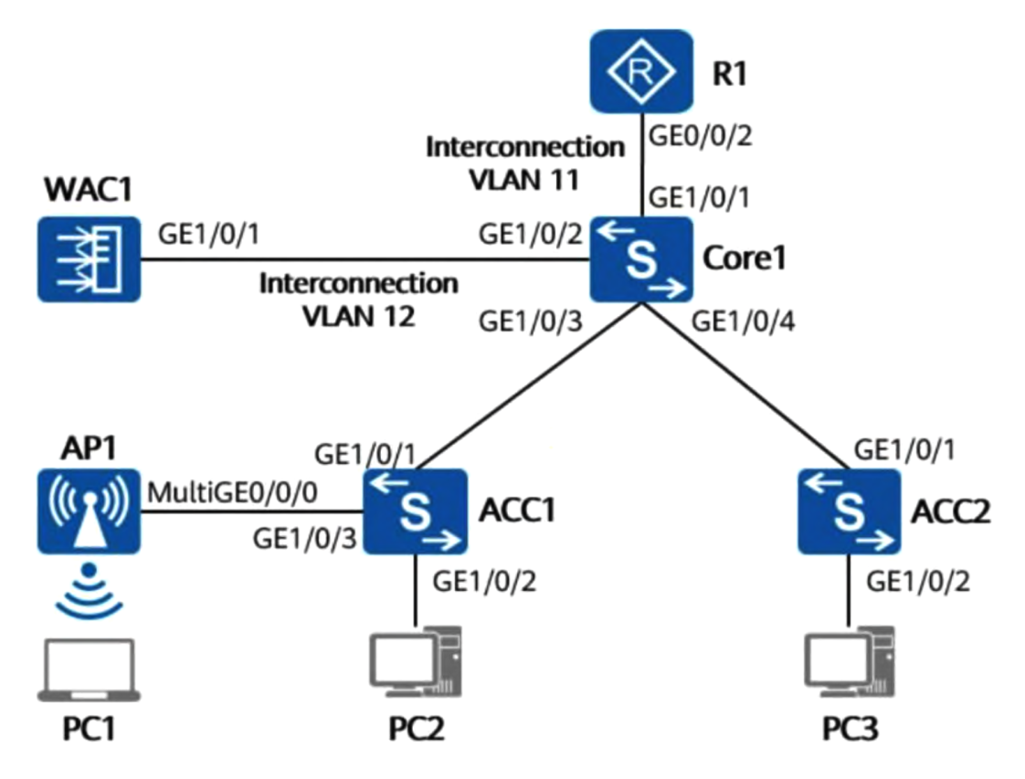
An option may be used more than once.
Drag & Drop
GE1/0/1 of ACC1
GE1/0/3 of ACC1
GE1/0/1 of ACC2
GE1/0/2 of Core1
GE1/0/3 of Core1
GE1/0/4 of Core1
Community Discussion